

Google Cloud offers Internal Load Balancing for your TCP/UDP-based traffic. Internal Load Balancing enables you to run and scale your services behind a private load balancing IP address that is accessible only to your internal virtual machine instances.
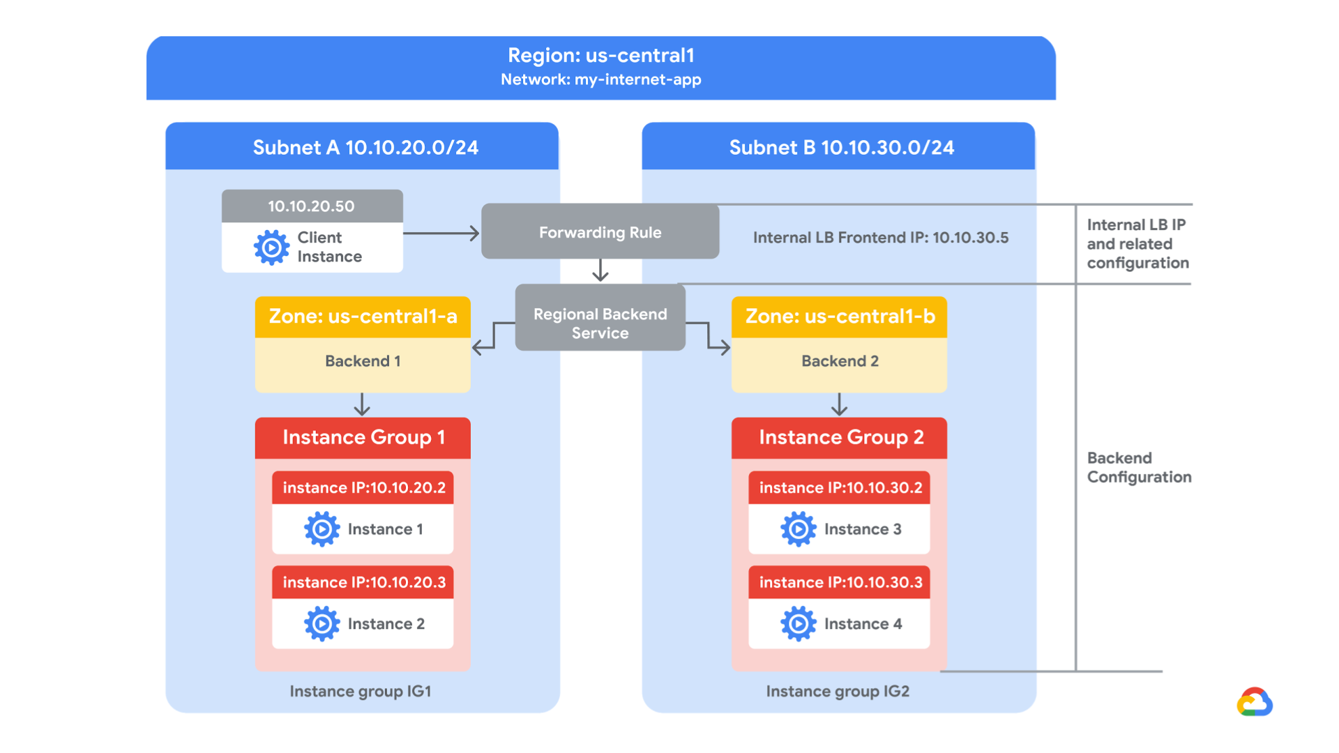
you create two managed instance groups in the same region. Then you configure and test an internal load balancer with the instances groups as the backends, as shown in this network diagram:
Objectives
In this lab, you learn how to perform the following tasks:
- Create internal traffic and health check firewall rules
- Create a NAT configuration using Cloud Router
- Configure two instance templates
- Create two managed instance groups
- Configure and test an internal load balancer
Task 1. Configure internal traffic and health check firewall rules.
Configure firewall rules to allow internal traffic connectivity from sources in the 10.10.0.0/16 range. This rule allows incoming traffic from any client located in the subnet.
Health checks determine which instances of a load balancer can receive new connections. For HTTP load balancing, the health check probes to your load-balanced instances come from addresses in the ranges 130.211.0.0/22 and 35.191.0.0/16. Your firewall rules must allow these connections.
Explore the my-internal-app network
The network my-internal-app with subnet-a and subnet-b and firewall rules for RDP, SSH, and ICMP traffic have been configured for you.
- In the Cloud Console, on the Navigation menu (
), click VPC network > VPC networks. Notice the my-internal-app network with its subnets: subnet-a and subnet-b.Each Google Cloud project starts with the default network. In addition, the my-internal-app network has been created for you as part of your network diagram.You will create the managed instance groups in subnet-a and subnet-b. Both subnets are in the us-central1 region because an internal load balancer is a regional service. The managed instance groups will be in different zones, making your service immune to zonal failures.
Create the firewall rule to allow traffic from any sources in the 10.10.0.0/16 range
Create a firewall rule to allow traffic in the 10.10.0.0/16 subnet.
- On the Navigation menu (
- Click Create Firewall Rule.
- Specify the following, and leave the remaining settings as their defaults:PropertyValue (type value or select option as specified)Namefw-allow-lb-accessNetworkmy-internal-appTargetsSpecified target tagsTarget tagsbackend-serviceSource filterIP RangesSource IP ranges10.10.0.0/16Protocols and portsAllow all
Make sure to include the /16 in the Source IP ranges.
- Click Create.
Create the health check rule
Create a firewall rule to allow health checks.
- On the Navigation menu (
- Click Create Firewall Rule.
- Specify the following, and leave the remaining settings as their defaults:PropertyValue (type value or select option as specified)Namefw-allow-health-checksNetworkmy-internal-appTargetsSpecified target tagsTarget tagsbackend-serviceSource filterIP RangesSource IP ranges130.211.0.0/22 35.191.0.0/16Protocols and portsSpecified protocols and ports
Make sure to include the /22 and /16 in the Source IP ranges.
- For tcp, specify port 80.
- Click Create.
Click Check my progress to verify the objective.
Configure internal traffic and health check firewall rulesCheck my progress
Task 2: Create a NAT configuration using Cloud Router
The Google Cloud VM backend instances that you setup in Task 3 will not be configured with external IP addresses.
Instead, you will setup the Cloud NAT service to allow these VM instances to send outbound traffic only through the Cloud NAT, and receive inbound traffic through the load balancer.
Create the Cloud Router instance
- In the Cloud Console, on the Navigation menu (
- Click Get started.
- Specify the following, and leave the remaining settings as their defaults:PropertyValue (type value or select option as specified)Gateway namenat-configVPC networkmy-internal-appRegionus-central1
- Click Cloud Router, and select Create new router.
- For Name, type nat-router-us-central1.
- Click Create.
- In Create a NAT gateway, click Create.
Wait until the NAT Gateway Status changes to Running before moving onto the next task.
Click Check my progress to verify the objective.
Create a NAT configuration using Cloud RouterCheck my progress
Task 3. Configure instance templates and create instance groups
A managed instance group uses an instance template to create a group of identical instances. Use these to create the backends of the internal load balancer.
Configure the instance templates
An instance template is an API resource that you can use to create VM instances and managed instance groups. Instance templates define the machine type, boot disk image, subnet, labels, and other instance properties. Create an instance template for both subnets of the my-internal-app network.
- On the Navigation menu (
- Click Create instance template.
- For Name, type instance-template-1
- Click Management, security, disks, networking, sole tenancy.
- Click Management.
- Under Metadata, specify the following:KeyValuestartup-script-urlgs://cloud-training/gcpnet/ilb/startup.sh
The startup-script-url specifies a script that is executed when instances are started. This script installs Apache and changes the welcome page to include the client IP and the name, region, and zone of the VM instance. You can explore this script here.
- Click Networking.
- For Network interfaces, specify the following, and leave the remaining settings as their defaults:PropertyValue (type value or select option as specified)Networkmy-internal-appSubnetworksubnet-aNetwork tagsbackend-serviceExternal IPNone
The network tag backend-service ensures that the firewall rule to allow traffic from any sources in the 10.10.0.0/16 subnet and the Health Check firewall rule applies to these instances.
- Click Create. Wait for the instance template to be created.Create another instance template for subnet-b by copying instance-template-1:
- Select the instance-template-1 and click Copy.
- Click Management, security, disks, networking, sole tenancy.
- Click Networking.
- For Network interfaces, select subnet-b as the Subnetwork.
- Click Create.
Create the managed instance groups
Create a managed instance group in subnet-a (us-central1-a) and subnet-b (us-central1-b).
- On the Navigation menu (
- Click Create Instance group.
- Specify the following, and leave the remaining settings as their defaults:PropertyValue (type value or select option as specified)Nameinstance-group-1LocationSingle-zoneRegionus-central1Zoneus-central1-aInstance templateinstance-template-1Autoscaling metrics > metrics type (Click the pencil edit icon)CPU utilizationTarget CPU utilization80Minimum number of instances1Maximum number of instances5Cool-down period45
Managed instance groups offer autoscaling capabilities that allow you to automatically add or remove instances from a managed instance group based on increases or decreases in load. Autoscaling helps your applications gracefully handle increases in traffic and reduces cost when the need for resources is lower. Just define the autoscaling policy, and the autoscaler performs automatic scaling based on the measured load.
- Click Create.Repeat the same procedure for instance-group-2 in us-central1-b:
- Click Create Instance group.
- Specify the following, and leave the remaining settings as their defaults:PropertyValue (type value or select option as specified)Nameinstance-group-2LocationSingle-zoneRegionus-central1Zoneus-central1-bInstance templateinstance-template-2Autoscaling metrics > metric type (Click the pencil edit icon)CPU utilizationTarget CPU utilization80Minimum number of instances1Maximum number of instances5Cool-down period45
- Click Create.
Verify the backends
Verify that VM instances are being created in both subnets and create a utility VM to access the backends’ HTTP sites.
- On the Navigation menu, click Compute Engine > VM instances. Notice two instances that start with instance-group-1 and instance-group-2.These instances are in separate zones, and their internal IP addresses are part of the subnet-a and subnet-b CIDR blocks.
- Click Create Instance.
- Specify the following, and leave the remaining settings as their defaults:PropertyValue (type value or select option as specified)Nameutility-vmRegionus-central1Zoneus-central1-fSeriesN1Machine typef1-micro (1 vCPU)Boot diskDebian GNU/Linux 10 (buster)
- Click Management, security, disks, networking, sole tenancy.
- Click Networking.
- For Network interfaces, click the pencil icon to edit.
- Specify the following, and leave the remaining settings as their defaults:PropertyValue (type value or select option as specified)Networkmy-internal-appSubnetworksubnet-aPrimary internal IPEphemeral (Custom)Custom ephemeral IP address10.10.20.50External IPNone
- Click Done.
- Click Create.
- Note that the internal IP addresses for the backends are 10.10.20.2 and 10.10.30.2.
If these IP addresses are different, replace them in the two curl commands below.
Click Check my progress to verify the objective.
Configure instance templates and create instance groupsCheck my progress
- For utility-vm, click SSH to launch a terminal and connect. If you see the Connection via Cloud Identity-Aware Proxy Failed popup, click Retry.
- To verify the welcome page for instance-group-1-xxxx, run the following command:
curl 10.10.20.2
content_copy
The output should look like this (do not copy; this is example output):
<h1>Internal Load Balancing Lab</h1><h2>Client IP</h2>Your IP address : 10.10.20.50<h2>Hostname</h2>Server Hostname:
 instance-group-1-1zn8<h2>Server Location</h2>Region and Zone: us-central1-a
content_copy- To verify the welcome page for instance-group-2-xxxx, run the following command:
curl 10.10.30.2
content_copy
The output should look like this (do not copy; this is example output):
<h1>Internal Load Balancing Lab</h1><h2>Client IP</h2>Your IP address : 10.10.20.50<h2>Hostname</h2>Server Hostname:
 instance-group-2-q5wp<h2>Server Location</h2>Region and Zone: us-central1-b
content_copy
Which of these fields identify the location of the backend?Server HostnameClient IPServer LocationSubmit
This will be useful when verifying that the internal load balancer sends traffic to both backends.
- Close the SSH terminal to utility-vm:
exit
content_copy
Task 4. Configure the internal load balancer
Configure the internal load balancer to balance traffic between the two backends (instance-group-1 in us-central1-a and instance-group-2 in us-central1-b), as illustrated in the network diagram:
Start the configuration
- In the Cloud Console, on the Navigation menu (
- Click Create load balancer.
- Under TCP Load Balancing, click Start configuration.
- For Internet facing or internal only, select Only between my VMs.
Choosing Only between my VMs makes this load balancer internal. This choice requires the backends to be in a single region (us-central1) and does not allow offloading TCP processing to the load balancer.
- Click Continue.
- For Name, type my-ilb.
Configure the regional backend service
The backend service monitors instance groups and prevents them from exceeding configured usage.
- Click Backend configuration.
- Specify the following, and leave the remaining settings as their defaults:PropertyValue (select option as specified)Regionus-central1Networkmy-internal-appInstance groupinstance-group-1 (us-central1-a)
- Click Done.
- Click Add backend.
- For Instance group, select instance-group-2 (us-central1-b).
- Click Done.
- For Health Check, select Create a health check.
- Specify the following, and leave the remaining settings as their defaults:PropertyValue (select option as specified)Namemy-ilb-health-checkProtocolTCPPort80
Health checks determine which instances can receive new connections. This HTTP health check polls instances every 5 seconds, waits up to 5 seconds for a response, and treats 2 successful or 2 failed attempts as healthy or unhealthy, respectively.
- Click Save and Continue.
- Verify that there is a blue check mark next to Backend configuration in the Cloud Console. If there isn’t, double-check that you have completed all the steps above.
Configure the frontend
The frontend forwards traffic to the backend.
- Click Frontend configuration.
- Specify the following, and leave the remaining settings as their defaults:PropertyValue (type value or select option as specified)Subnetworksubnet-bInternal IPReserve a static internal IP address
- Specify the following, and leave the remaining settings as their defaults:PropertyValue (type value or select option as specified)Namemy-ilb-ipStatic IP addressLet me chooseCustom IP address10.10.30.5
- Click Reserve.
- For Ports, type 80.
- Click Done.
Review and create the internal load balancer
- Click Review and finalize.
- Review the Backend and Frontend.
- Click Create. Wait for the load balancer to be created before moving to the next task.
Click Check my progress to verify the objective.
Configure the Internal Load BalancerCheck my progress
Task 5. Test the internal load balancer
Verify that the my-ilb IP address forwards traffic to instance-group-1 in us-central1-a and instance-group-2 in us-central1-b.
Access the internal load balancer
- On the Navigation menu, click Compute Engine > VM instances.
- For utility-vm, click SSH to launch a terminal and connect.
- To verify that the internal load balancer forwards traffic, run the following command:
curl 10.10.30.5
content_copy
The output should look like this (do not copy; this is example output):
<h1>Internal Load Balancing Lab</h1><h2>Client IP</h2>Your IP address : 10.10.20.50<h2>Hostname</h2>Server Hostname:
 instance-group-1-1zn8<h2>Server Location</h2>Region and Zone: us-central1-a
content_copy
As expected, traffic is forwarded from the internal load balancer (10.10.30.5) to the backend.
- Run the same command a couple of times:
curl 10.10.30.5
curl 10.10.30.5
curl 10.10.30.5
curl 10.10.30.5
curl 10.10.30.5
curl 10.10.30.5
curl 10.10.30.5
curl 10.10.30.5
curl 10.10.30.5
curl 10.10.30.5
content_copy
You should be able to see responses from instance-group-1 in us-central1-a and instance-group-2 in us-central1-b. If not, run the command again.
Task 6. Review
Here you created two managed instance groups in the us-central1 region and a firewall rule to allow HTTP traffic to those instances and TCP traffic from the Google Cloud health checker. Then you configured and tested an internal load balancer for those instance groups.